Basic Material Testing
Introduction
Typical laboratory equipment can be used to measure dielectric, elastic, and piezoelectric constants for piezoceramics. MIL-STD (military standard) 1376B, ANSI/IEEE Standard 176-1987, and European Standard EN 50324:2002, as well as IRE Standards on Piezoelectric Crystals (1961), all describe their preferred methods for taking measurements. Some of those step-by-step procedures are described here for the familiar constants listed below.
- Coupling Factors k33 k3 kp
- Free Relative Dielectric Constant K3T
- Dissipation Factor (Low field) D or tan δ
- Elastic-Compliances SD33 SE33 SD11 SE11
- Piezoelectric d and g constants d33 g33 d31 g31
- Mechanical Q Qm
Test Specimens
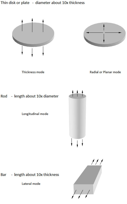
Samples of various specific shapes are used to avoid large errors in determining some of the constants. Determining different constants require the use of various different shapes. These shapes often do not include the practical shapes found in transducers, because they are not appropriate for measuring many of the constants. Three different shape configurations (as shown in Fig. 1) are required to measure all the above listed constants.
Measurements
The measurements that must be performed on the test specimens are:
- Weight – or Density
- Physical dimensions
- Free capacitance and dissipation factor – (low field)
- Frequency of minimum impedance and frequency of maximum impedance
- The magnitude of the minimum impedance.
The data obtained from these measurements are used to calculate the various constants.
Equipment
To perform these measurements, the following equipment is required:
- Laboratory balance capable of weighing to accuracy of about 1 milligram.
- Micrometer(s) with range(s) to measure all dimensions of the test specimens.
- Capacitance (and dissipation) bridge capable of covering the range of about 10 pf to 10,000 pf with accuracy of better than 1%.
- Impedance analyzer capable of covering the frequency range of about 100 KHz to 10 MHz with an accuracy of about 1%.
- Quasi-static d33 meter such as a ‘Berlincourt’ meter.
Measurement Procedure
The steps necessary to determine the constants are as follows:
- From Fig. 1, select specimen shape or shapes required for the constants to be determined.
- Make the measurements indicated below. See the following paragraphs for detailed instructions.
- Calculate the constants from the measured data as explained in detail later in this report.
Measurement of Weight
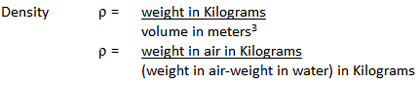
Weigh the test specimen in air. This is required, together with dimensions, for determination of density. If preferred, the density may be determined by weighing the specimen in air and then in water by the method of Archimedes.
Measurement of Dimensions
Measure the dimensions of the test specimen with a micrometer. It is advisable to measure at several points and use the averages of these measurements.
Measurement of Capacitance and Dissipation
Measure the capacitance C and the dissipation factor D at 1 KHz. Keep the test voltage across the specimen below: 100 x (distance between electrodes measured in inches) volts.
Measurement of Frequencies of Minimum and Maximum Impedances
Sweep frequency over the expected resonant frequency of the part geometry being tested. Choose a range of approximately +/- 20% around this frequency. Determine the frequency at which the impedance is at a minimum and where it is at a maximum over this range.
Measurement of Magnitude of Minimum Impedance
The set up for this measurement is the same as for the measurement of frequencies of minimum impedance. Measure the value at the minimum point and record this value as Zm.
Calculations
Calculation of Density
The density in Kilograms/cubic meter is required in later calculations.
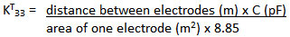
Calculation of Free Relative Dielectric Constant KT33
This is calculated from the measured values of capacitance and physical dimensions of the specimen.
Calculation of Coupling
Coupling is calculated from the frequencies of minimum and maximum impedances. The applicable formula depends on the vibration mode as shown below. The frequencies of minimum and maximum impedances are not the exact frequencies required for these calculations, and a small correction theoretically should be made as described in the IRE Standards. However, when dealing with Lead Zirconate-Lead Titanate compositions, the error resulting from omitting the correction is not significant. Accordingly, the corrections generally are not made and will not be included here.
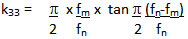
Calculation of Coupling k33
This is applicable only to length poled rods as shown in Fig. 1.
Calculation of Coupling k31
This is applicable only to long, slim thickness Poled specimens as shown in Fig. 1.

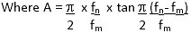
Calculation of Coupling kp
This is applicable only to thin discs as shown in Fig. 1.
Calculate: (fn – fm) / fm
Use the curve Fig. 8 to determine kp. Fig. 8 is valid only for piezoelectric ceramic having Poisson's ratio near 0.3. Presently available Lead Titanate-Lead Zirconate compositions meet this requirement.
Calculation of Elastic Constants
Elastic constants are calculated from the frequency controlling dimension, density, and the frequencies of minimum or maximum Impedance as shown below. Physical dimensions must be in meters.
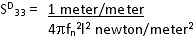
Calculation of Coupling SD33
This is applicable only to length poled rods as shown in Fig. 1.
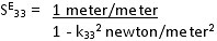
Calculation of Coupling SE33
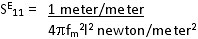
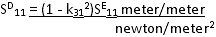
Calculation of Coupling SE11
This is applicable only to long, slim, thickness poled specimens as shown in Fig. 1.
Calculation of Coupling SD11
Calculation of Piezoelectric Constants
The d and g constants are calculated from values of coupling, dielectric constant, and elastic constant previously calculated.
Calculation of Piezoelectric Constant d33
Calculation of Piezoelectric Constant d31
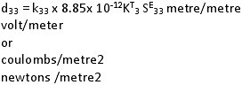
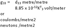
Calculation of Piezoelectric Constant g33
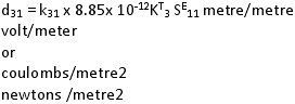
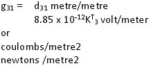
Calculation of Piezoelectric Constant g31
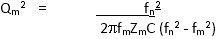
Calculation of Mechanical Q
This is calculated from the frequencies on minimum and maximum impedance, the magnitude of the minimum impedance, and capacitance.
Piezo Basics
- Origin of the Piezo Effect
- Material Families
- Basic Material Testing
- Tolerances and Capabilities
- Modes of Vibration (PDF)
- Glossary of Terms